A Computer Vision Problem
Original problem statement file and required files here. This problem was given to me in my sophomore year as a task under my tenure in the ARK perception team.
I haven’t done robotics in a long while (am writing this thing after leaving all that stuff behind), this being the only testimony of me having done those courses on image processing lol.
Problem Statement
If none of the following make sense to you and those text files seem like random jargon, this post is NOT for you. Go and move on, you’re better off not knowing about all this altogether (unless you want to pursue a career in robotics, maybe)
A breif version of the problem goes like this-
- given 30 files, 10 each of types 0 (RGB, jpg), 1 (Segmentation, jpg) and 2 (Pose, txt)
- images are 256x144 in size
- a projective pinhole camera is used everywhere
- camera has a horizontal field-of-view (FOV) of 90°
- assumptions-
- the distortion parameters are zero
- principal point of the image is at its center
- focal length in x direction = focal length in y direction
- pose data is the position of the camera in the world coordinates in the NED coordinate system
- it is stored in the form of an orientation quaternion and a position vector
Objective
Using the information provided, calculate
- length of the side of the cube
- x,y,z coordinates of the centroid of the cube
Initial Attempt
I started to recall everything that I’d gone through while doing my courses. Thought about applying all sorts of stuff like homography, constructing the camera matrices, using stereo pairs (seemed illogical at that time).
My line of thought only seemed to go in one direction- use all images separately.
But then I hit a dead wall when I couldn’t convert the 2D coordiantes to 3D ones (was the essence of the entire problem). I thought maybe the information given was insufficient and I needed a scale factor.
The whole 3D -> 2D conversion eats up the depth information completely, hence a (x y z) -> (x’ y’) mapping exists. However to do the opposite, you need to materialize the depth information from somewhere.
But then again, I wasn’t using all the information provided to me, hinting towards my shortcoming.
My solution approach
Get em curves, ehm corners
I started to think of some use case to the segmentation masks provided. I had to locate corners in tha image according to image coordiantes. So there it was, I used the segmentation masks, ran them through the Harris corner detector function of OpenCV.
The results were good honestly,
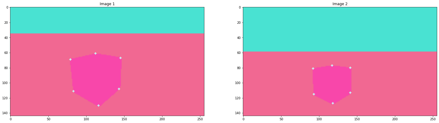
but
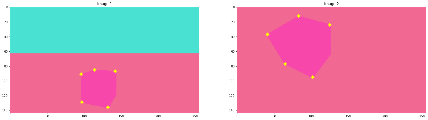
Hmm, but hey I had many coresponding points atleast.
2D -> 3D
There are a few ways in which you can achieve this. The simplest being tracing out lights rays from the corners to the center of the camera (possible with the given pose data) and then finding the intersection.
But then this method is bound to introduce noise. You’ll never be sure about the intersection at all. In fact you might even will have to find the point of minimum distance instead. Because, in robotics, error and noise are gonna be your arch nemesis always. Consequenty, a large part of your time will often be invested with dealing with the error.
I had to use Triangulation. All what remained was to simulate the thing1 on the actual problem.
Evil matrices
The key step behind all of this to work appreciably was- not screwing up simple calculation. Simple, right?
Funnily enough, I managed to screw up the calculation each time I made the extrinsic and intrisic matrices. Why? Because the best values I could come up with were-
- 55.75492842884244
- 66.53124150897686
- 73.18385840990788
- 9.655399061410336
These are supposed to be side lenghts of the cube :clown:. Another run of the simulation yielded side lenghts of the order of 10^-3 to 10^3 (in the same set :clown: :clown:).
My best guess to where I was going wrong back then would be direction of axes and the position of the 2D origin (I don’t remember, even if I did, I wouldn’t reveal it like that ofc) But then I also remember checking my camera parameters like for the N^th time.
I even tried plotting the 3D coordinates after tweaking the paramteres like a bazillion times, only to get this
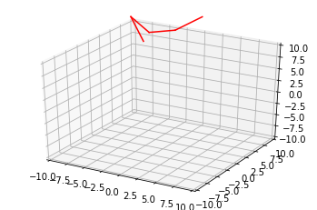
This, well this is supposed to be a face of the cube, which should be, idk, slightly squarish I guess? (Even the ground corner coordinates didn’t seem to go along the NED direction thing)
Double checked it with my peers at ARK, asked the seniors about the validity of pose data only to hit a dead end.
Result
There were no results, I couldn’t solve it.
However after this thing was over and we were discussing about it, turns out one of us at ARK did indeed manage to get a very tight approximate.
I’ll just quote the solution algorithm he followed here.
ML and approximation
ML algorithms in their core are essentially complex approximation methods. Interestingly we can apply a well known method to get to the solution here.
Gradient descent, get a parametric equation for the original complicated equation and bam a very clean solution.
Coming directly from his repo’s README.md
The final approach was to create a parametric model for a cube in 3D space lying on a horizontal surface. Such a cube is sufficiently described by 5 parameters - the x, y, z coordinates of its centroid, the angle of rotation about the vertical (z-axis), and the side length. The parameterization used has s as the semi side length for a cleaner formula representation. The corners of this cube can be found in terms of these parameters and keys/color descriptors can be assigned in cyclic order. These keys were manually assigned, although it is possible to automatically assign them using the detected color data. With this description, the distance of each corner can be found to all the corresponding projection lines and the sum of the squares of these distances is taken as a loss function. Tensorflow is then used to automatically differentiate and optimize the values of these parameters using the Adam optimizer.
Here’s the link to his repo